London Lathe

Figure 1: London lathe manufactured in London, Ontario, Canada, circa 1890.
My London lathe was built by the London Machine Tool Works in London, Ontario, Canada. I don’t know the date of manufacture, but the structure and style of the lathe suggests pre-1900. According to the following sources, the London Machine Tool company was founded by William Yeates and operated in London, Ontario from 1882 to 1905 when the company was moved to Hamilton, Ontario. In 1912, London Machine Tool was purchased by the Canadian Machine Corporation (CMC) and operations were consolidated in Galt, Ontario.
http://www.vannattabros.com/iron55.html
http://vintagemachinery.org/mfgindex/detail.aspx?id=3209
The old London is a good rigid machine that will handle heavy turnings. Its 2.375” spindle runs in large bronze journals. The spindle centre bore is 1.25” and the taper is MT4.5. The original tailstock taper was MT3.5, but I rebored the tailstock to the more standard MT4 taper. Fitted with my custom drive based on a Ford Ranger 5-speed transmission, the lathe has spindle speeds of approximately 160, 270, 390, 590, and 740 rpm. The back-gear ratio is 8.52. Engaging the back-gear reduction expands the range to 10 speeds and reduces the low speed to approximately 19 rpm. The high-speed of 740 rpm is definitely on the high side for an antique lathe, but with copious light oil lubrication on the journals, the 3 HP motor will achieve full speed.

Figure 2: London lathe manufactured in London, Ontario, Canada, circa 1890.
The lathe pre-dates standard quick-change gearboxes for thread pitch selection. A train of individually swappable change gears once drove a lead screw for threading. When I purchased this lathe, its lead screw and all change gears were missing, so this machine does not thread. Its original threading capacity is shown on the brass plate of Figure 3. I once intended to make a lead screw and a set of gears, but that low priority project dropped so low in my priority list as to have almost no possibility of ever happening. I use this lathe occasionally for large diameter turnings. It has a swing of 18”, and I have it equipped with a 4-jaw 16” chuck. Given the heft of the chuck, I am not inclined to change it often, so the lathe is mostly relegated to large diameter 4-jaw work that does not require thread cutting. Centre to centre turning capacity would be about 60”, but the previous owner stripped half of the rack mounted on the bed for the rack-and-pinion mechanism of the carriage. This reduces the carriage travel, so I can only turn about 30” between centres. Another low priority project that may never escape the vision stage is to make a rack to recover the full travel of the lathe carriage.
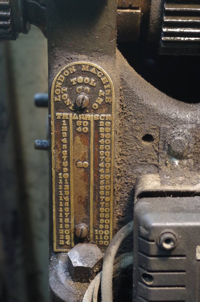
Figure 3: Original brass identification badge with threading chart.
The headstock was intended for flat belt drive from an overhead countershaft, but I adapted the lathe to V-belt drive by machining a ring to fit over one of the flat belt pulley steps (Figure 4). A sufficient center opening in the bed allowed a belt to drop through to couple to the output of a Ford Ranger 5-speed transmission mounted beneath the lathe. The Ranger transmission is driven by a 3 HP motor (Figure 5). To guide the belt through the narrow channel of the bed, I made and installed some custom brackets with idler pulleys on the interior of the bed (Figure 6).

Figure 4: The flat-belt headstock with custom V-belt drive ring installed and keyed to the flat-belt pulley. The lathe is a relic from the overhead countershaft era when often a single large shaft running the length of the factory served multiple machines. The prime mover may have been a large electric motor or, in earlier times, a steam engine.
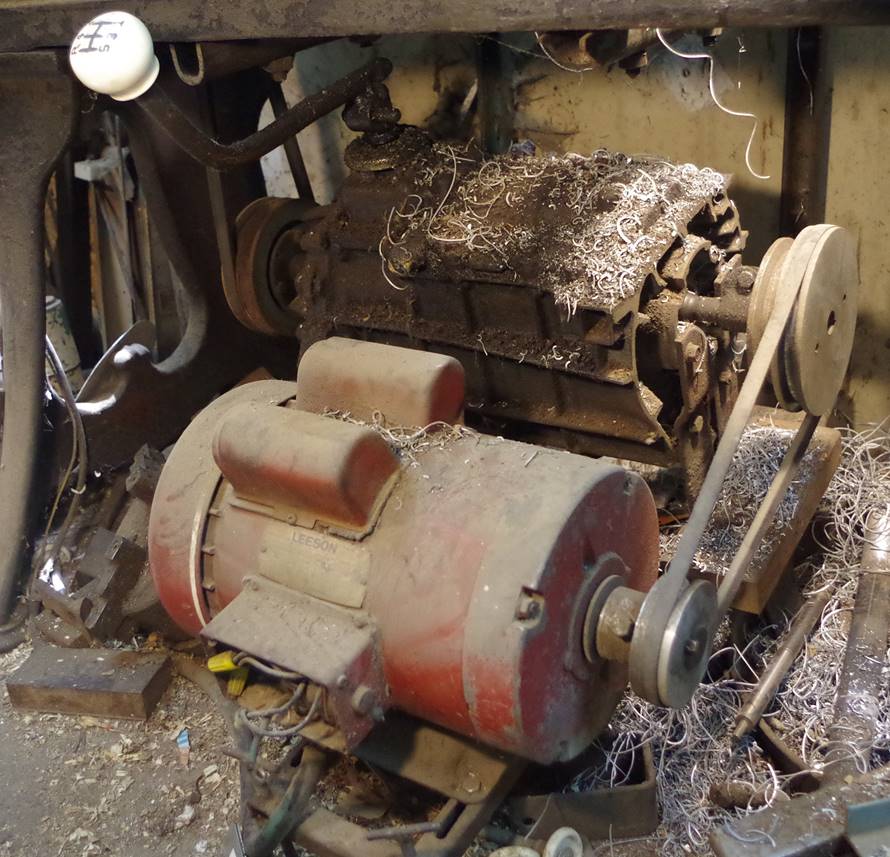
Figure 5: London lathe drive assembly: 3HP Leeson 220V single-phase motor driving a Ford Ranger 5-speed automobile transmission.
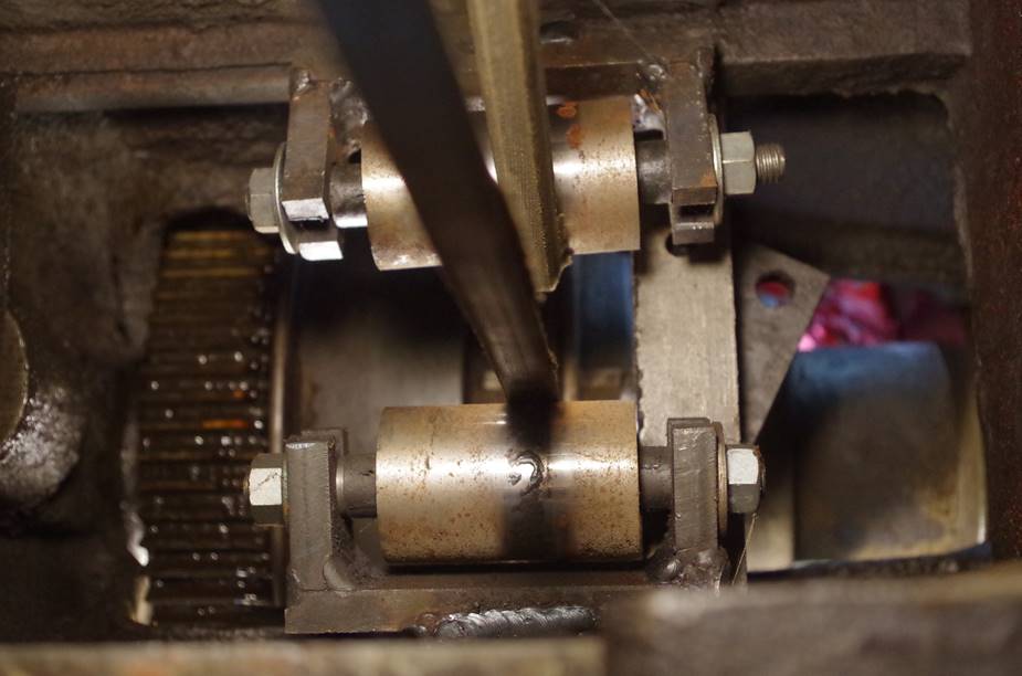
Figure 6: The idler pulley arrangement guiding the belt through the bed. The view is from underneath the lathe looking up.
The original lathe did not have a compound slide, but simply a fixed slide, so I adapted a surplus compound slide scavenged from an old Smith & Mills shaper. An adapter plate bolted to the top of the shaper slide allows a conventional lathe tool holder to be accommodated. I discarded the original lathe fixed slide, replacing it with my steel weldment machined with the matching dovetail angle and a machined circular plate on the top to accept the shaper slide. The compound pivots a full 360o guided by a central hub bushing and locked down by the bolts running in circular T-slots. The compound has about 5” of travel.
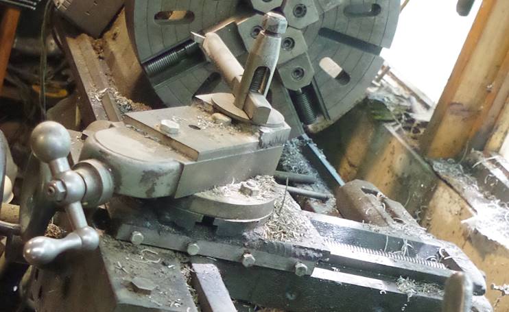
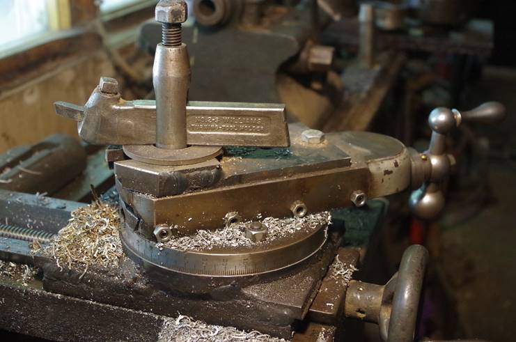
Figure 7: Compound slide adapted from a Smith and Mills shaper. The compound is mounted on a custom-built steel weldment machined with matching dovetails for the cross-slide and a circular top surface with circular T-slots to allow the shaper slide to pivot 360o. The angle graduations were scribed by Smith and Mills.